Our client produces compounds required in the manufacture of polymers, a flourishing growth industry. It was planned to build a new plant to increase production capacity. However the installation of a new unit adjoining the old called for integration of the new design with as-built plans of the latter – which had never previously been produced …
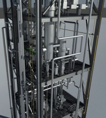
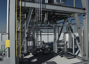
For this project in which the new unit would bear directly on the old, it was necessary to ensure that the overall structure could withstand the extra loading of the additional plant. This included a check on wind bracing of the structure ; the existing structural framework required computational analysis before any such work could be planned. The whole steel framework was very dense, and crowded with equipment and pipework. Our survey would inevitably be hampered by multiple obstructions. The only possible choice of method was 3D laser scanning.
Laser scans were carried out around the unit at ground level and on each of the six levels. They were then georeferenced in the coordinate system of the whole works in order to integrate them into the client’s database of drawings and plans. The combined point cloud consisted of 20 million spatially referenced points.
Modelling takes place in several stages. The overall structure is given by the 3D model of the structural steel framework in which different types of profile (angles and sections such as HE, IPN, UPN, etc., with their dimensions including steel thickness and depth) are identified semi-automatically from the point cloud. The extraction of pipework data is also controlled by the workstation operator. Once the pipework itself has been been identified, the point cloud is automatically replaced by standardised cylinders and elbow shapes. It should be noted that accuracy checking between modelled components and the point cloud is carried out continuously (standard deviation for each object).
Valves, flanges, vents and other point features are identified in the point cloud and their positions are adjusted to fit the alignments of the linear components. The user of the model can both follow the entire length of a system of pipework and take account of future modifications.
The exchange format which we have chosen for this project is Cyclone Object Exchange (COE), which offers several advantages:
 |
 |
3D model file in COE format for MicroStation, exact replica of the existing plant, classified by function and conforming to standard symbolisation (pipework, structural steel)
Contact
Follow us
|
|
ZA Champ du roy. 219 chem. des goules 38670 Chasse-sur-rhône |