In order to satisfy the increasing demand for natural gas, the operator of a gas field decided to debottleneck part of its offshore installation.
For this part of the installation, no plan existed which was both complete and accurate. The engineers asked TPLM-3D to carry out laser scanner surveys and to produce as-built plans.
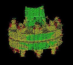
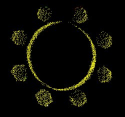
We were given eight hours to carry out the whole survey on site. We proceeded as follows: we scanned the pipework from six instrument stations with a density of points sufficient to model the bolts on the flanges (that is, the alignments of the drill holes as stipulated in the technical specification). The tubing, flanges and bolts were all scanned at high density. The two illustrations show the high definition of the scans of DN 80 and DN 125 pipes.
 |
 |
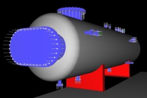
The Cyclone software (Leica Geosystems) replaces the point cloud with predefined components (tabulated in accordance with ANSI pipework standards); the workstation operator does however check each modelled piping component. The flanges are then modelled and aligned with the pipes which emerge from them, then the drill holes are deduced from the bolts, directly within the point cloud, and are constructed perpendicular to the faces of the flanges.
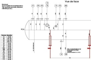
The result of this first stage is a 3D model which is exported in DWG format so as to be dimensioned and reduced to three orthogonal 2D plots. The plots are produced through AutoCAD, starting from the 3D model and generating specific thematic layers (tubulars, drill holes, equipment, alignments, etc.). The pipes are shown on the three orthogonal viewswith their nominal diameters (DN) and the positions of the drill holes.
 |
 |
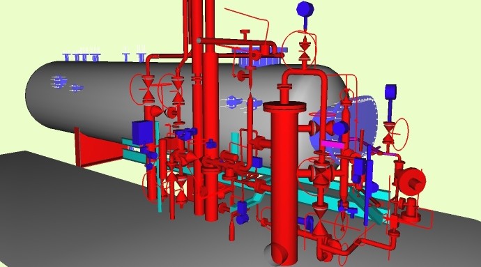
Carrying out a laser scanner survey rather than direct measurement of specific positions gives the survey a structure which is comprehensive and adaptable. Not only the pipework but all of the equipment is scanned, thereby enabling the modelling of the complete and very complex assembly of pipes and other apparatus. This modelling was the subject of a supplementary request by the engineers, who needed to check the available clearances between all of this equipment in order to incorporate the additional pipework required for the new process.
A single measurement campaign was sufficient for several models covering different areas. Site visits were thus optimised and reduced to a minimum.
Contact
Follow us
|
|
ZA Champ du roy. 219 chem. des goules 38670 Chasse-sur-rhône |