A dispute between the owner and the contractor responsible for construction of a slab on an industrial site (a distribution centre). We were tasked with checking the work carried out by the contractor.
|
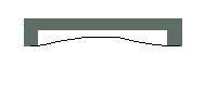
The flatness of the slab was specified as “Class I” (maximum 3mm departure from flatness over 2 m, the strictest of the four classes covered by the French national standard for concrete structures, DTU 21 – NF P 18-201). Our task was to carry out the necessary checks in a systematic and accurate manner over the whole extent of the slab. Historically, flatness checks have relied on a rigid 2- or 3-metre bar or straight-edge, resting on two pegs, one fixed at each end of the bar, together with a third moveable peg. The length of each peg is set to the admissible tolerance. The checking process consists of placing the bar at different positions over the slab. Several cases are possible:
|
||
| Case n°1 : The two fixed pegs rest on the slab ; the moveable peg cannot pass under the bar. |
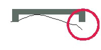
Case n°2 : One of the two fixed pegs stands clear of the slab. |
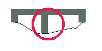
Case n°3 : The two fixed pegs touch the slab but the moveable one can pass under the bar in some places but not everywhere. |
 |
 |
 |
| [Source: ispentreprise.be] | ||
This procedure can be tedious and time-consuming if the slab is to be checked thoroughly.
In the spirit of the R&D policy of TPLM-3D, we developed a new and rapid tool for flatness checking and acceptance of slabs and screeds. A very precise digital copy of the slab is produced and then subjected to a computer simulation of the 2-metre-rule procedure.
The slab data was captured in four stages (for internal organisational reasons at the distribution centre). The challenge for us was to guarantee reliable and homogeneous results, accurate to 2 mm, when the four surveys were combined. The slab is defined by several million points, one every 3 to 4 cm, thus providing an extremely realistic representation of the whole. By using appropriate computation procedures on the captured point cloud, we are able to bring the accuracy of our survey to the required 2 mm. In parallel with the laser scans, the emplacement of permanent reference points and their meticulous measurement was of fundamental importance in guaranteeing results at this level of accuracy. This systematic use of computational rather than manual procedures enabled the identification and unambiguous recording of out-of-tolerance points.
The final result is thus an AutoCAD file showing the position of every such point. Several colour-coded layers within AutoCAD indicate different categories of point : in the example shown here, grey and blue for high points and green and yellow for hollows.
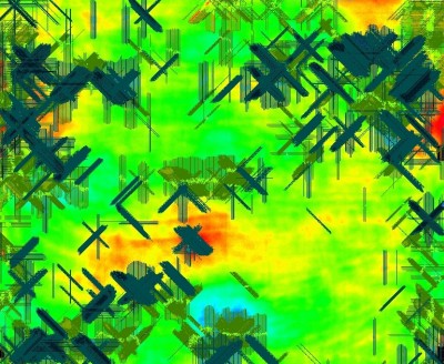
To provide an overview of the deformations, we also supply a colour-coded map with contours at equal intervals. This cartographic representation provides an image which is easy to interpret.
1 simulated 2-metre-rule flatness analysis in the form of an AutoCAD plot in DWG and PDF formats
Contact
Follow us
|
|
ZA Champ du roy. 219 chem. des goules 38670 Chasse-sur-rhône |