On 25th August 2000 an inter-departmental (French government) circular imposed new standards on highway tunnels. The objective was to improve traffic safety in tunnels and to reinforce the protection of the surrounding natural environment.
The necessary renovation of the north tube of the tunnel, for which our work was commissioned, required almost six months’ work. No aspect of the existing tunnel conformed to the new standards, so the first months of work involved a massive civil engineering effort.
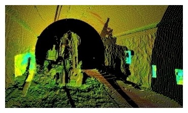
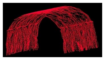
TPLM-3D was not only involved during the civil engineering phase, but also during the demolition of the existing side walls and the false ceiling. Because the schedule for reopening the motorway was very tight, work took place 24 hours per day, 6 days per week. To optimise the time on site, targets were placed and observed by the engineering consortium’s own surveyor. Our surveys could thus be integrated into the coordinate system already in place in the tunnel. We used the HDS 3000 scanner (producing 360°×270°scans), to survey 400 m of tunnel with an average density of one point every 5 cm. These point clouds, captured in one night’s work, were then combined and georeferenced to the existing coordinate system thanks to the targets bolted into the rock. This provided a 3D triangular irregular network (TIN or mesh) which then provided the basis for :
 |
 |
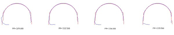
To guarantee adherence to the specified tolerances, we took special care both with the choice of points for the TIN and with the method of generating it, in order to eliminate measurement noise and especially in order to provide checks on the resulting model.
In this way the transition from point cloud data (faithful to reality but unusable by the client) to the 3D mesh model was managed so as to provide the best possible compromise between density of information, file size and accuracy, thus generating the optimum result.
Contact
Follow us
|
|
ZA Champ du roy. 219 chem. des goules 38670 Chasse-sur-rhône |