This ship was built in 1930. An investigation of its stability was required, in addition to a major refit including engine replacement.
The majority of the plans of the ship were obsolete, and no drawings existed for the shape of the hull itself. To produce them, the design office needed profiles and sections faithfully representing the shape of the vessel from the top of the hull to the bottom of the keel.
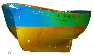
We carried out a laser scanner survey (Leica HDS 3000) with an average density of one point every 5 cm over the whole hull (one point per cm for the stern, the rudder and the bottom of the keel). The ship was supported on a line of blocks. Six instrument stations were occupied around the hull, to produce a high-density point cloud from each. Targets were emplaced on the hull itself and on the inside of the dry dock in order to provide a common reference system for the six point clouds. The aim was to obtain a single homogeneous system and an accuracy of the order of 5 mm.
This point cloud was filtered before processing, in order to eliminate at the outset any obviously incorrect points, as well as gangways and scaffolding, persons interrupting the line of sight, sacrificial anodes, supporting blocks, etc. In parallel, the coordinate system was fixed so as to be aligned with the geometry of the ship:
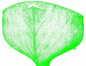
From the point cloud to the 3D mesh (triangular irregular network or TIN)
Everything is done in stages! The first stage is to create a triangular irregular network (TIN or mesh) from the point cloud, such that sections and plans can then be generated automatically. This is a key stage because the high precision of the point cloud must be preserved while greatly reducing the volume of data: 900 000 points can be reduced to around 275 000 triangles. The main difficulty is to retain accurate geometry in the TIN, whatever the local geometry of the hull. The triangles must be of high density around geometrically complex parts of the hull (including stabilisers, the rudder, etc.), while smoother, curved areas require far fewer triangles. This stage is controlled entirely by software (3DReshaper). The resulting TIN is essential for the automatic generation of the required profiles and sections.
 |
 |
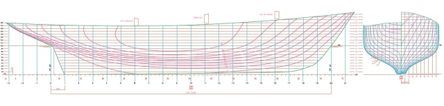
From the 3D mesh to the sheer and body plans (longitudinal and transverse sections)
Having already defined the coordinate system in accordance with the principal axes of the hull, it is necessary only to specify the interval between sections. The final result is two sets of layered 3D polylines in DXF format. These provide the basis for reconstructing the shape of the hull.
Our client uses Autoship software. He extracts the sets of longitudinal profiles and transverse sections (which yield the sheer plan and body plan respectively) from the 3D triangular mesh, thereby recreating the shape with 3D splines.
Contact
Follow us
|
|
ZA Champ du roy. 219 chem. des goules 38670 Chasse-sur-rhône |